Merchandise Description
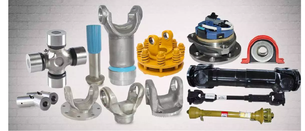
HangZhou Xihu (West Lake) Dis. Cardanshaft Co.,LTD is a leading expert company of cardan shafts in China. Our firm has targeted on the research and development, style and manufacture of the oil equipment cardan shafts for 15 a long time.
The cardan shafts of various sorts are extensively utilized in domestic large oil enterprises this kind of as Sinopec, PetroChina Xihu (West Lake) Dis. Oilfield Organization, HangZhouang Tarim Oilfield Business, HangZhou Chinese oil ,and other domestic oil production enterprises.Now it is out of the place, the goods are exported to North The united states, the Middle East and other locations. The layout of the common shaft employed in the 70L, 50L, 80L and other drilling rigs, which includes the turntable common shafts, diesel motor universal shafts, mud pump universal shafts.
Oil wells are in the area of production, the generation environment is incredibly negative, and it is tough to ensure the universal shafts for more than one hundred eighty times of uninterrupted operate. To this conclude, our company specifically created the cross axis assembly of the sealing construction, virtually attained the servicing totally free. In addition, in accordance to the customers’ different sorts of requestments, specific connection modes of universal shafts with substantial coaxial, adaptable joints, effortless installation, best soon after-income provider are made.
The subsequent table for SWC Medium-sized Universal Shaft Parameters.
Designs
Knowledge and Dimensions of SWC Collection Common Joint Couplings
| Kind | Layout Data Merchandise |
SWC160 | SWC180 | SWC200 | SWC225 | SWC250 | SWC265 | SWC285 | SWC315 | SWC350 | SWC390 | SWC440 | SWC490 | SWC550 | SWC620 |
| A | L | 740 | 800 | 900 | one thousand | 1060 | 1120 | 1270 | 1390 | 1520 | 1530 | 1690 | 1850 | 2060 | 2280 |
| LV | 100 | one hundred | one hundred twenty | one hundred forty | one hundred forty | a hundred and forty | a hundred and forty | 140 | 150 | one hundred seventy | 190 | 190 | 240 | 250 | |
| M(kg) | 65 | eighty three | one hundred fifteen | 152 | 219 | 260 | 311 | 432 | 610 | 804 | 1122 | 1468 | 2154 | 2830 | |
| B | L | 480 | 530 | 590 | 640 | 730 | 790 | 840 | 930 | a hundred | 1571 | 1130 | 1340 | 1400 | 1520 |
| M(kg) | 44 | 60 | 85 | one hundred ten | a hundred and sixty | one hundred eighty | 226 | 320 | 440 | 590 | 820 | 1090 | 1560 | 2100 | |
| C | L | 380 | 420 | 480 | 500 | 560 | 600 | 640 | 720 | 782 | 860 | 1040 | 1080 | 1220 | 1360 |
| M(kg) | 35 | forty eight | sixty six | 90 | a hundred thirty | 160 | 189 | 270 | 355 | 510 | 780 | 970 | 1330 | 1865 | |
| D | L | 520 | 580 | 620 | 690 | 760 | 810 | 860 | 970 | 1030 | 1120 | 1230 | 1360 | 1550 | 1720 |
| M(kg) | 48 | sixty five | 90 | 120 | 173 | 220 | 250 | 355 | 485 | 665 | 920 | 1240 | 1765 | 2390 | |
| E | L | 800 | 850 | 940 | 1050 | 1120 | 1180 | 1320 | 1440 | 1550 | 1710 | 1880 | 2050 | 2310 | 2540 |
| LV | one hundred | one hundred | a hundred and twenty | one hundred forty | one hundred forty | one hundred forty | a hundred and forty | 140 | 150 | one hundred seventy | 190 | a hundred ninety | 240 | 250 | |
| M(kg) | 70 | ninety two | 126 | 165 | 238 | 280 | 340 | 472 | 660 | 886 | 1230 | 1625 | 2368 | 3135 | |
| Tn(kN·m) | sixteen | 22.4 | 31.five | 40 | 63 | 80 | 90 | one hundred twenty five | 180 | 250 | 355 | five hundred | 710 | one thousand | |
| TF(kN·m) | 8 | eleven.two | 16 | twenty | 31.5 | forty | 45 | 63 | 90 | one hundred twenty five | one hundred eighty | 250 | 355 | five hundred | |
| Β(°) | 15 | 15 | 15 | 15 | fifteen | fifteen | fifteen | 15 | fifteen | 15 | fifteen | 15 | 15 | fifteen | |
| D | 160 | a hundred and eighty | two hundred | 225 | 250 | 265 | 285 | 315 | 350 | 390 | 440 | 490 | 550 | 620 | |
| Df | one hundred sixty | 180 | two hundred | 225 | 250 | 265 | 285 | 315 | 350 | 3690 | 440 | 490 | 550 | 620 | |
| D1 | 137 | a hundred and fifty five | 170 | 196 | 218 | 233 | 245 | 280 | 310 | 345 | 390 | 435 | 492 | 555 | |
| D2(H9) | a hundred | 105 | a hundred and twenty | a hundred thirty five | 150 | one hundred sixty | a hundred and seventy | 185 | 210 | 235 | 255 | 275 | 320 | 380 | |
| D3 | 108 | 114 | one hundred forty | 159 | 168 | one hundred eighty | 194 | 219 | 245 | 273 | 299 | 325 | 402 | 426 | |
| Lm | 95 | 105 | one hundred ten | one hundred twenty five | 140 | a hundred and fifty | a hundred and sixty | one hundred eighty | 195 | 215 | 260 | 270 | 305 | 340 | |
| K | sixteen | seventeen | eighteen | twenty | twenty five | 25 | 27 | 32 | 35 | 40 | forty two | 47 | 50 | 55 | |
| T | 4 | 5 | five | 5 | 6 | six | seven | eight | eight | eight | ten | twelve | twelve | twelve | |
| N | 8 | eight | eight | 8 | eight | eight | eight | 10 | ten | ten | 16 | 16 | 16 | 16 | |
| D | 15 | 17 | 17 | 17 | 19 | 19 | 21 | 23 | 23 | 25 | 28 | 31 | 31 | 38 | |
| B | twenty | 24 | 32 | 32 | 40 | 40 | 40 | forty | fifty | 70 | 80 | 90 | a hundred | a hundred | |
| G | 6. | 7. | nine. | 9. | 12.five | 12.five | twelve.5 | 15. | sixteen. | eighteen. | twenty. | 22.five | 22.five | 25 | |
| MI(Kg) | 2.fifty seven | three | three.eighty five | 3.eighty five | 5.seventeen | 6 | 6.seventy five | 8.twenty five | 10.six | 13 | eighteen.fifty | 23.75 | 29.12 | 38.08 | |
| Size | M14 | M16 | M16 | M16 | M18 | M18 | M20 | M22 | M22 | M24 | M27 | M30 | M30 | M36 | |
| Tightening torque(Nm) | a hundred and eighty | 270 | 270 | 270 | 372 | 372 | 526 | 710 | 710 | 906 | 1340 | 1820 | 1820 | 3170 |
one. Notations:
L=Common length, or compressed length for styles with length compensation
LV=Duration compensation
M=Weight
Tn=Nominal torque(Produce torque fifty% in excess of Tn)
TF=Tiredness torque, I. E. Permissible torque as determined according to the tiredness strength
Under reversing loads
β=Greatest deflection angle
MI=bodyweight per 100mm tube
2. Millimeters are utilized as measurement models other than where noted
3. Please consult us for customizations concerning length, size compensation and
Flange connections.
(DIN or SAT etc. )
| Material: | Alloy Steel |
|---|---|
| Load: | Drive Shaft |
| Stiffness & Flexibility: | Stiffness / Rigid Axle |
| Journal Diameter Dimensional Accuracy: | IT6-IT9 |
| Axis Shape: | Straight Shaft |
| Shaft Shape: | Hollow Axis |
###
| Customization: |
Available
|
|---|
###
| Type | Design Data Item |
SWC160 | SWC180 | SWC200 | SWC225 | SWC250 | SWC265 | SWC285 | SWC315 | SWC350 | SWC390 | SWC440 | SWC490 | SWC550 | SWC620 |
| A | L | 740 | 800 | 900 | 1000 | 1060 | 1120 | 1270 | 1390 | 1520 | 1530 | 1690 | 1850 | 2060 | 2280 |
| LV | 100 | 100 | 120 | 140 | 140 | 140 | 140 | 140 | 150 | 170 | 190 | 190 | 240 | 250 | |
| M(kg) | 65 | 83 | 115 | 152 | 219 | 260 | 311 | 432 | 610 | 804 | 1122 | 1468 | 2154 | 2830 | |
| B | L | 480 | 530 | 590 | 640 | 730 | 790 | 840 | 930 | 100 | 1010 | 1130 | 1340 | 1400 | 1520 |
| M(kg) | 44 | 60 | 85 | 110 | 160 | 180 | 226 | 320 | 440 | 590 | 820 | 1090 | 1560 | 2100 | |
| C | L | 380 | 420 | 480 | 500 | 560 | 600 | 640 | 720 | 782 | 860 | 1040 | 1080 | 1220 | 1360 |
| M(kg) | 35 | 48 | 66 | 90 | 130 | 160 | 189 | 270 | 355 | 510 | 780 | 970 | 1330 | 1865 | |
| D | L | 520 | 580 | 620 | 690 | 760 | 810 | 860 | 970 | 1030 | 1120 | 1230 | 1360 | 1550 | 1720 |
| M(kg) | 48 | 65 | 90 | 120 | 173 | 220 | 250 | 355 | 485 | 665 | 920 | 1240 | 1765 | 2390 | |
| E | L | 800 | 850 | 940 | 1050 | 1120 | 1180 | 1320 | 1440 | 1550 | 1710 | 1880 | 2050 | 2310 | 2540 |
| LV | 100 | 100 | 120 | 140 | 140 | 140 | 140 | 140 | 150 | 170 | 190 | 190 | 240 | 250 | |
| M(kg) | 70 | 92 | 126 | 165 | 238 | 280 | 340 | 472 | 660 | 886 | 1230 | 1625 | 2368 | 3135 | |
| Tn(kN·m) | 16 | 22.4 | 31.5 | 40 | 63 | 80 | 90 | 125 | 180 | 250 | 355 | 500 | 710 | 1000 | |
| TF(kN·m) | 8 | 11.2 | 16 | 20 | 31.5 | 40 | 45 | 63 | 90 | 125 | 180 | 250 | 355 | 500 | |
| Β(°) | 15 | 15 | 15 | 15 | 15 | 15 | 15 | 15 | 15 | 15 | 15 | 15 | 15 | 15 | |
| D | 160 | 180 | 200 | 225 | 250 | 265 | 285 | 315 | 350 | 390 | 440 | 490 | 550 | 620 | |
| Df | 160 | 180 | 200 | 225 | 250 | 265 | 285 | 315 | 350 | 3690 | 440 | 490 | 550 | 620 | |
| D1 | 137 | 155 | 170 | 196 | 218 | 233 | 245 | 280 | 310 | 345 | 390 | 435 | 492 | 555 | |
| D2(H9) | 100 | 105 | 120 | 135 | 150 | 160 | 170 | 185 | 210 | 235 | 255 | 275 | 320 | 380 | |
| D3 | 108 | 114 | 140 | 159 | 168 | 180 | 194 | 219 | 245 | 273 | 299 | 325 | 402 | 426 | |
| Lm | 95 | 105 | 110 | 125 | 140 | 150 | 160 | 180 | 195 | 215 | 260 | 270 | 305 | 340 | |
| K | 16 | 17 | 18 | 20 | 25 | 25 | 27 | 32 | 35 | 40 | 42 | 47 | 50 | 55 | |
| T | 4 | 5 | 5 | 5 | 6 | 6 | 7 | 8 | 8 | 8 | 10 | 12 | 12 | 12 | |
| N | 8 | 8 | 8 | 8 | 8 | 8 | 8 | 10 | 10 | 10 | 16 | 16 | 16 | 16 | |
| D | 15 | 17 | 17 | 17 | 19 | 19 | 21 | 23 | 23 | 25 | 28 | 31 | 31 | 38 | |
| B | 20 | 24 | 32 | 32 | 40 | 40 | 40 | 40 | 50 | 70 | 80 | 90 | 100 | 100 | |
| G | 6.0 | 7.0 | 9.0 | 9.0 | 12.5 | 12.5 | 12.5 | 15.0 | 16.0 | 18.0 | 20.0 | 22.5 | 22.5 | 25 | |
| MI(Kg) | 2.57 | 3 | 3.85 | 3.85 | 5.17 | 6 | 6.75 | 8.25 | 10.6 | 13 | 18.50 | 23.75 | 29.12 | 38.08 | |
| Size | M14 | M16 | M16 | M16 | M18 | M18 | M20 | M22 | M22 | M24 | M27 | M30 | M30 | M36 | |
| Tightening torque(Nm) | 180 | 270 | 270 | 270 | 372 | 372 | 526 | 710 | 710 | 906 | 1340 | 1820 | 1820 | 3170 |
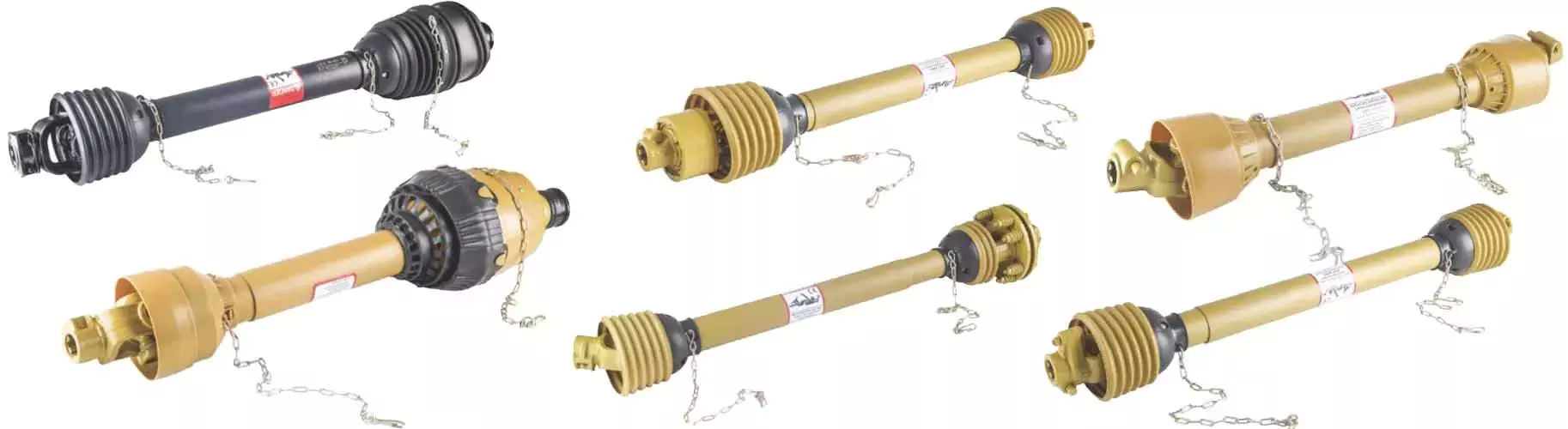
Power Take-Off (PTO) Shafts
Power take-off (PTO) shafts are used on many types of machines, including jet aircraft. They are typically semi-permanently mounted to a marine or industrial engine, and are powered by a drive shaft. The drive shaft also powers secondary implements and accessories. Depending on the application, accessory drives may also be used in aircraft. There are four main types of PTO units used in jet aircraft.
Power take-off (PTO) shaft
 The power take-off (PTO) shaft of a tractor can be controlled to operate in one of two modes: automatic and manual. Automatic mode operates when the PTO shaft starts turning and is automatically engaged when the power lift is raised by actuating the lift lever 9. Manual mode operates when the lift lever is not raised.
The manual mode allows for manual adjustments. A retaining band 12 may be adjusted arcuately about PTO shaft S with an axial center parallel to the axis of the PTO shaft S. The retaining band may be secured by conventional over center clamps. The retaining band 12 may also be adjusted arcuately about pin or bolt 30.
Power take-off (PTO) shaft safety retainers are used to prevent unintended disconnection of the PTO shaft. The safety retainers comprise a stationary openable band that circumscribes the PTO shaft near the connection with driven machinery. The band is preferably offset from the axis of the PTO shaft.
While the PTO shaft is a convenient way to transfer mechanical power to farm implements, there are several inherent hazards associated with using it improperly. Accidental disconnections of the PTO shaft pose a significant risk for the operator. A disconnect can cause the PTO shaft to whip around the driven machinery, potentially causing injury.
Power take-off shaft entanglements can be devastating to the limbs trapped in them, requiring amputation in some cases. In addition to being dangerous, the PTO shafts must be fully guarded to prevent contact with the ground. A farmer must never get too close to an operating PTO shaft to protect their own safety.
Types
There are several different types of PTO shafts available to suit various applications. They can vary in size and number of splines. Each standard has a specific speed range and is designed to fit a variety of implements. For example, there are German and Italian types of PTO shafts.
The type of PTO shaft you choose will determine the maximum load that can be safely transferred. Depending on the type, the rate at which the PTO clutch engages will be different. For example, a lower-density PTO shaft will engage at a slower rate than a higher-density PTO shaft, while a higher-density shaft will be more tolerant of higher loads.
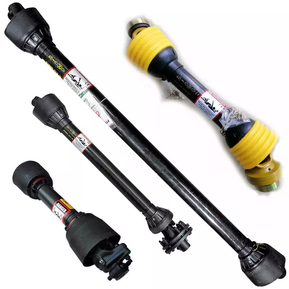
The primary function of a PTO shaft is to secure equipment to the tractor or other agricultural equipment. These parts often feature safety shields on both ends. They are also made in the same shape as the secondary shaft. The front shaft is wider than the secondary shaft, which allows the secondary shaft to fit inside. However, during movement, pieces of the PTO shaft can collapse, making them less safe.
PTO shafts are expensive and easy to steal, so make sure to protect your investment. Make sure the PTO shaft has guards to protect it from thieves. There are two types of PTO shafts: the external and the internal PTO yokes. Internal PTO shafts have an internal PTO yoke, while external PTO shafts use a universal joint. There is also a safety chain and shield on the external PTO shaft.
Depending on the application, you can choose between several different kinds of PTO shafts. Some types of PTO shafts have multiple splines, which can increase the torque transmitted. For applications requiring accuracy and precision, you may want to use a parallel keyed shaft.
Connections
 A PTO shaft has two parts: an input and an output. The input portion of a PTO adapter shaft has a smaller diameter, and the output portion has a larger diameter. Both are connected by splines. These splines have tapered outer ends. The first bore 25 has a first frustoconical wall, while the second bore has a second frustoconical wall.
One of the most common causes of PTO shaft failure is a poorly adjusted clutch. Another common cause is improper lubrication of the PTO shaft’s wide angle joints. PTO shafts should be lubricated at least once every eight hours. If you fail to do this, you risk premature ware and reduced life expectancy.
When a PTO shaft is installed in a tractor, the tractor must be connected to the implement using a coupler frame. The coupler frame has a PTO adapter mounting flange that engages with the PTO stub shaft. The coupler frame can move to accommodate the PTO adapter shaft, and the PTO adapter shaft can pivot and slide with the coupler frame.
When a PTO shaft fails, it can result in damage to the tractor and implement. Identifying the cause will help you fix the problem. Constant compression of the PTO shaft can damage the connecting shafts and connections. This could damage the tractor or implement, resulting in expensive repairs. When this happens, it is important to cut or shorten the shaft to reduce the risk of damage.
PTO shaft 24 extends rearward from tractor 10 and is connected to the front universal joint 28 and first end of variable-length splined drive shaft 32. The shaft is connected to a drive mechanism 36 on a mobile work implement 34. This drive mechanism may be mechanical, hydraulic, or a combination of both.
Safety
It is very important for every person using a tractor to understand the safety of PTO shafts. PTOs can be extremely dangerous, and without the correct shielding, they can cause serious injury. It can also be very dangerous if someone accidentally steps on or falls on one while the machine is operating. This is why it is important for everyone using a tractor to read the manufacturer’s manual and follow the safety guidelines for PTO shafts. Moreover, PTOs must only be used for the purpose intended.
PTO safety should be the number one priority for every operator. A small child was tragically killed when he became entangled with a spinning PTO shaft. His father tried to pull him out of the shaft, but was unable to do so. His clothing, which was near the spinning shaft, caught on the PTO and dragged him into it. His body was thrown around the shaft several times, and he sustained injuries to his leg, right arm, and head.
The PTO shaft is an important part of a tractor, and is used to secure the equipment. It is usually secured by safety shields on both ends. There are several kinds of safety shields. One type is a shield that is attached to the front of the PTO shaft. Another type is a shield that rotates freely on its bearings.
Power takeoffs are common on most small and compact tractors, construction machinery, and other equipment. They rotate to provide the drive for the equipment. However, the PTO shaft is very dangerous because it can easily catch something that gets too close to it. Moreover, loose items can also get tangled around the PTO shaft.
Maintenance
 One of the most important things to do in order to keep your PTO shaft in top condition is to keep it properly greased. This can be done by using a grease gun or a hand pump. It is important to keep the grease fresh and apply it in the appropriate amounts depending on how much you use the PTO. It is also important to separate the primary and secondary shafts and remove any debris from them.
It is also important to check the spline threads on your PTO on a periodic basis. This is important because some signs of dry shafts are not always immediately apparent. Similarly, spline threading and corrosion can occur behind the scenes and go undetected. Proper PTO maintenance is a vital part of safe and efficient operation.
A damaged or worn drive shaft will prevent your car from turning freely, leaving you exposed to higher repair bills. In addition, it will drastically affect the performance of your car. A broken drive shaft can even result in a crash. You should take your vehicle to a mechanic as soon as you notice any of these problems.
Fortunately, most PTO-driven equipment is equipped with a shear pin to prevent collisions and prevent damage to the gearbox and shaft. It should also be replaced regularly to prevent excessive wear. Long bolts pose a risk of entanglement and can easily catch clothing or gloves. For safety reasons, it is important to disengage the PTO when not in use.
Another thing to do is to keep the PTO shields clean. They must be regularly rotated and tested. Always ensure that your drawbar is properly configured for your machine. This prevents stressing or separating the driveline.

editor by czh 2022-12-23